ATSAMD SWD PROGRAMMER/2022
The global chip scarcity in 2022 made us reliant on the ATSAMD11C14A chip. Because the AtTiny 412 or the 1614 were nowhere to be sourced from, so on our lab we decided to go with the SAMD11C chip.
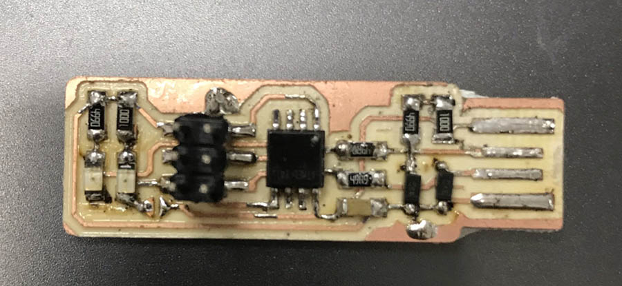
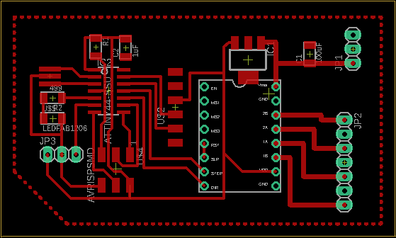
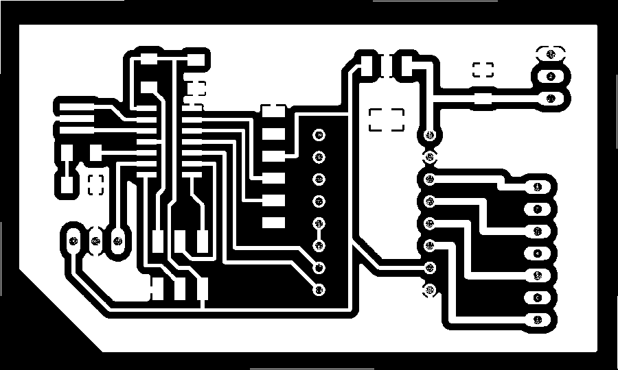
I decided to go with the FAB SWD programmer mainly because the ease of use - we don't have many 10 wire connectors in our lab so this one works well for us. Even better, the SWD D11C - RST fix version has the least components of them all -no LEDs though. It only has to 2 capacitors, one rsistor and one regulator, apart from the header pins, USB connector and the chip itself.
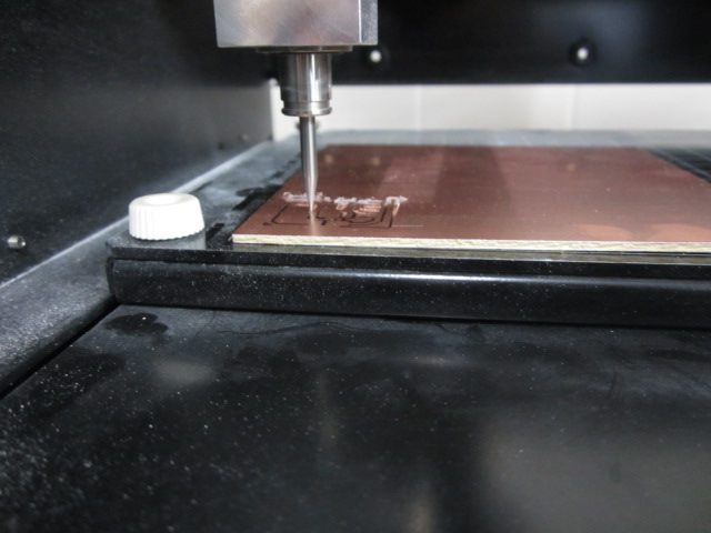
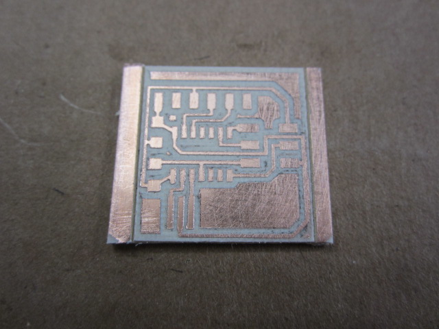
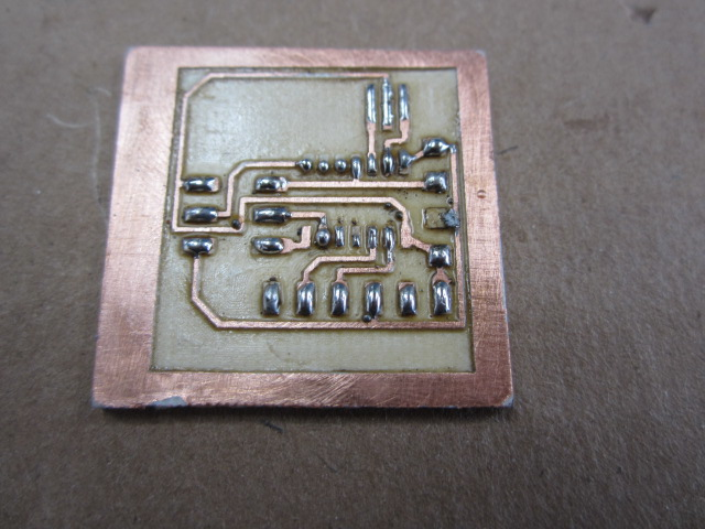
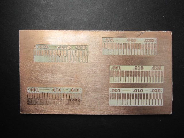
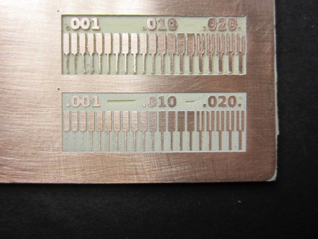
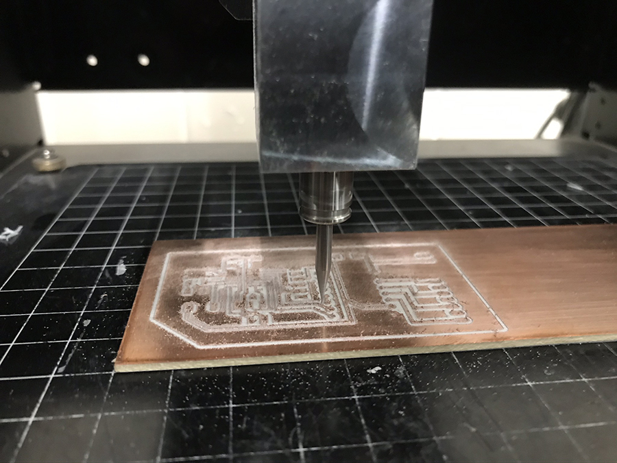
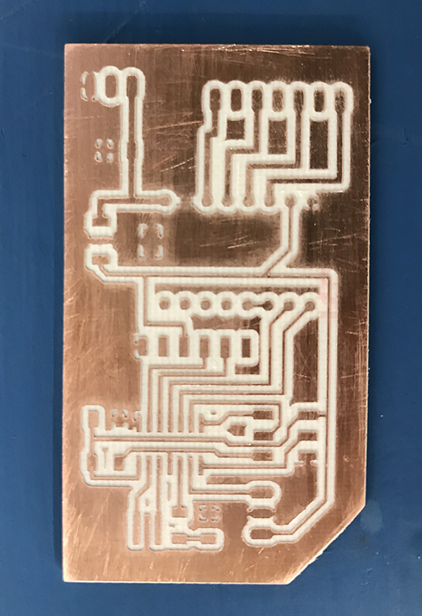
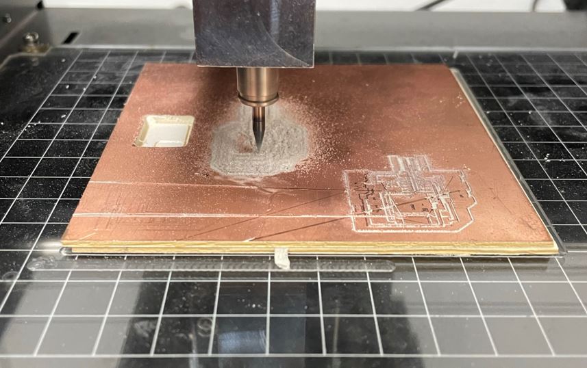
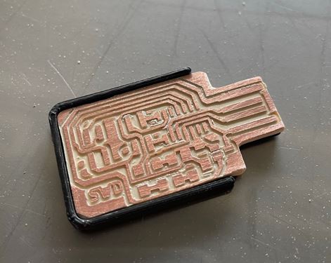
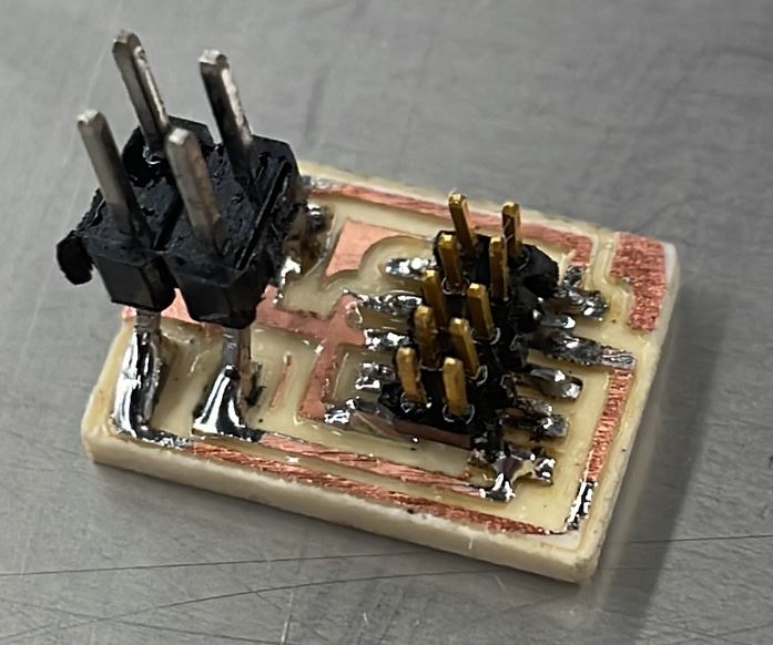
I actually made both, here is the milled board, please see here for details on milling using our MDX-20.
Here is the first one aling with the 3d printed raft:

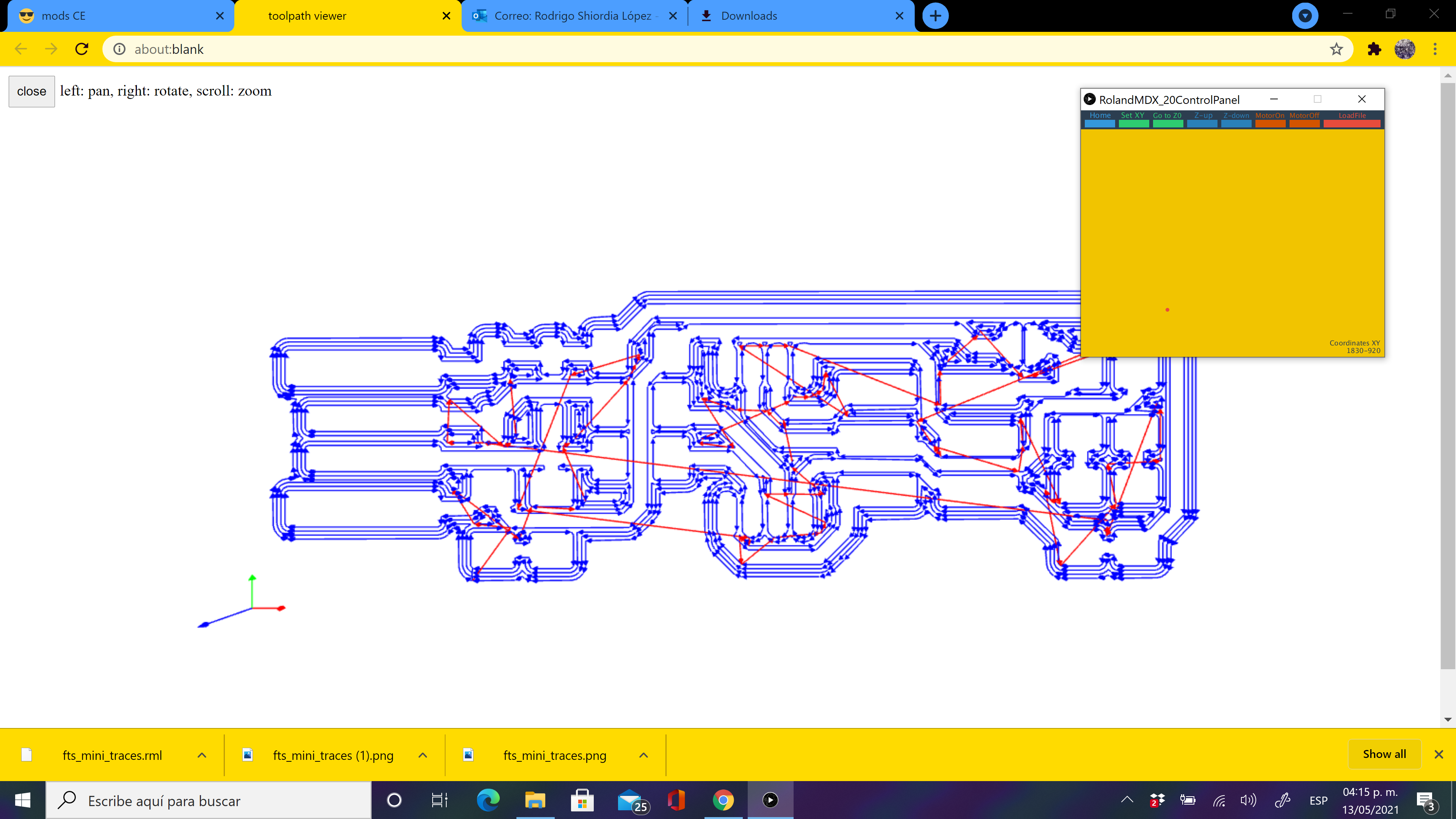
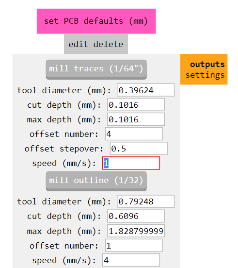
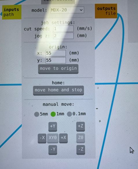
We used MODS CE for generating toolpaths and sending to the machine. Here is a quick screen grab of the settings.
For some reason I couldn't program it using EDBG and the ICE programmer. I only had success using OPEN OCD
Here are the steps to program it:
- 1:Download OpenOCD: I downloaded the Linux version easily using:
sudo apt install openocd
- 2: Download openocd configuration file: Download OPEN OCD configuration
*.cfgfile from here. The configuration file specifies the target chip(SAMD11C), interface(CMSIS-DAP), and binary(see below)to program. - 3:Download binary: Download the FreeDap Programmer binary from here to the same directory as the configuration file from the last step.
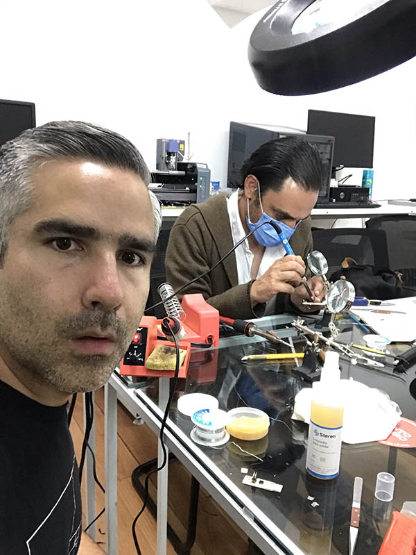
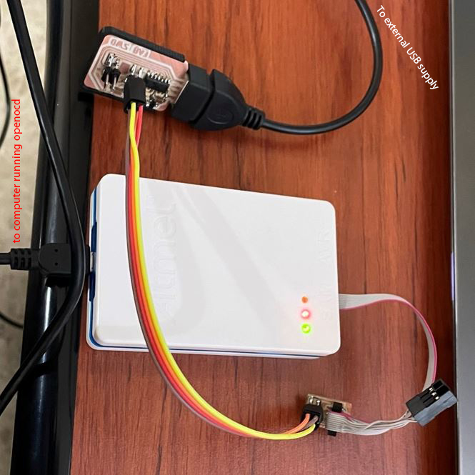
- 4: Connect the board and programmer: Connect the board to the Atmel ICE programmer using the 10-4 adapter. Connect the Atmel ICE to your computer. Remember to connect the USB on the board to an external usb (not the same computer):
- 5:Flash the board: Run
openocdon the same directory.
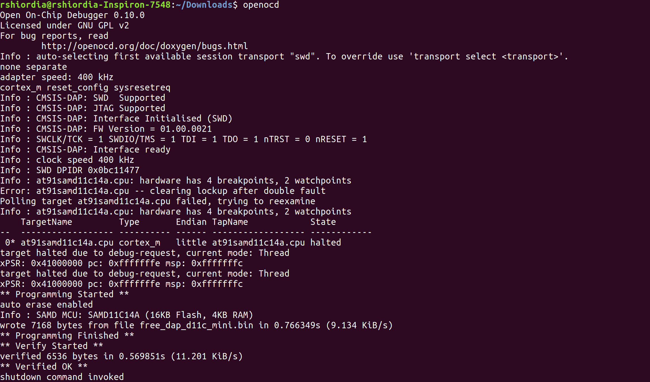
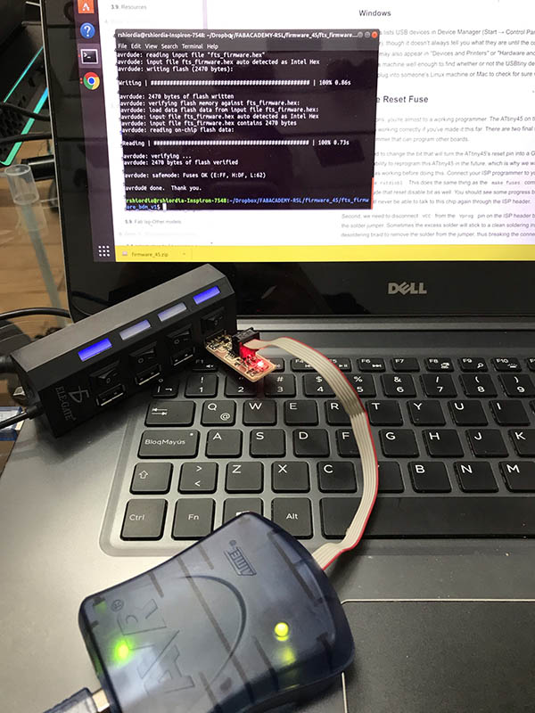
- 6: Verify: As I said, I tried doing this with EDBG, but wasn't able to do it, but openocd worked. However, once this programmer is flashed, EDBG does recognize it. You can check it using
edbg -lwhich should show you the available programmers and you should see your new CMSIS-DAP:

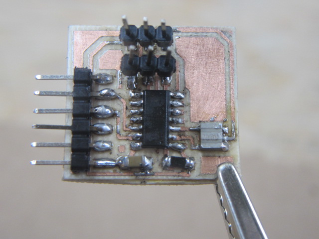
With my programmerdone, I made another programmer. The reason I made two is because the first issue with Atmel ICE not working with EDBG.
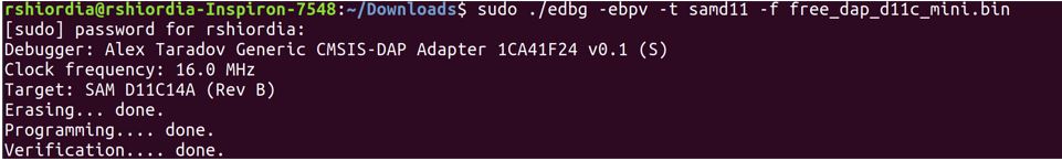
Since I had the programmer at hand I decided to try my programmer using EDBG. And it worked!!:
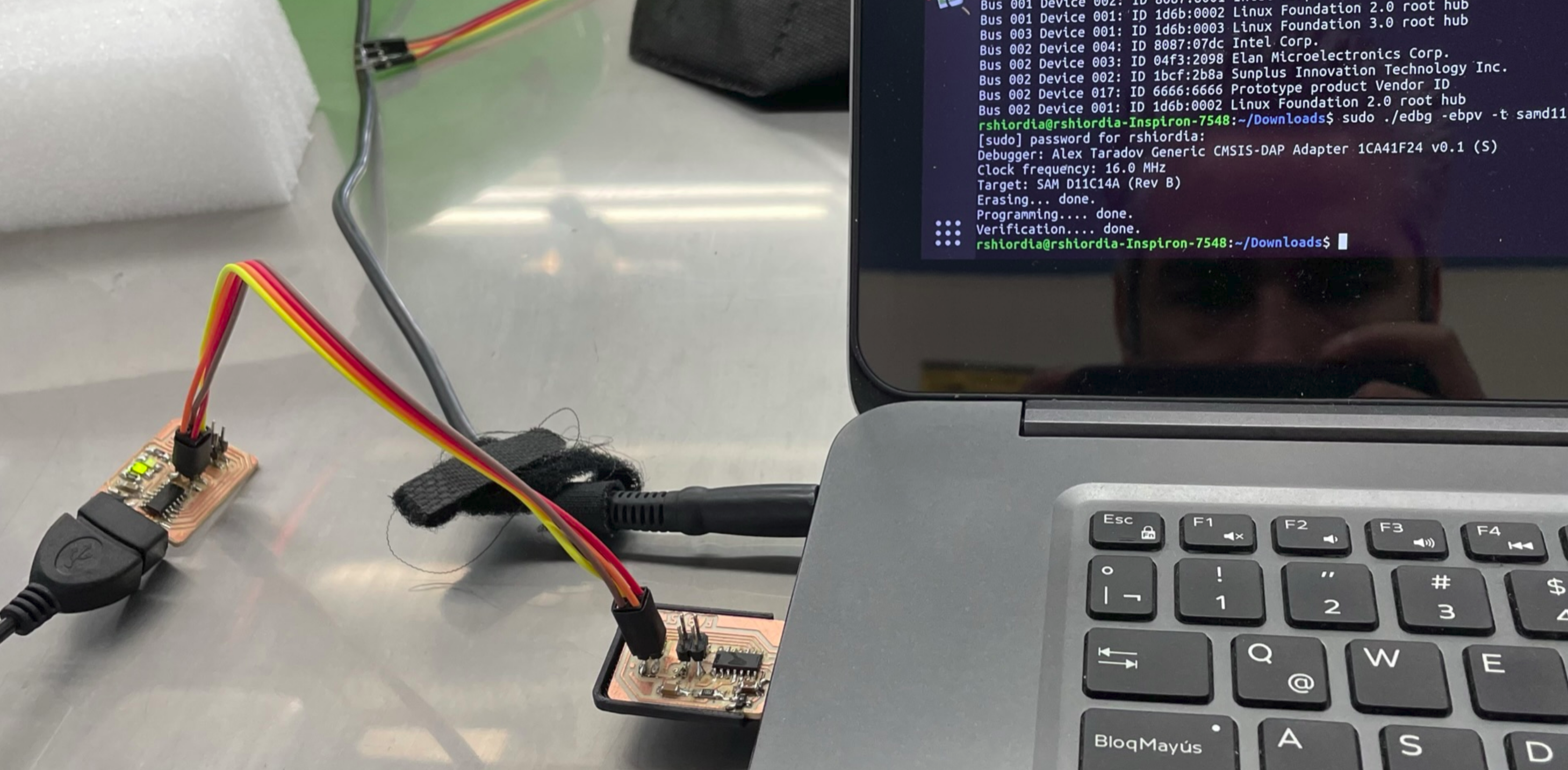
I used this code to flash it:
edbg -ebpv -t samd11 -f free_dap_d11c_mini.bin